SO...I've been doing
a lot more research on H-vac's and have discovered a few things that will very likely pertain to the K5's.
I went into the MT-53D K6/7 book to check a few things and found there were up to 9 different units used.Discounting the tandems,COE's & bus chassis narrows it down to 4. Depending on chassis number a truck can have a 1st,2nd or 3rd series unit and they are all different from the other. That being the case it's
very probable the same goes for the other K's equipped with H-vac's.
I could
really use the master cylinder (Fig.1205) & H-vac (Fig.1210) pages (including the illustrations) from the MT-52D. I ID'd 4 used on the 6/7's and can probably do the same for the others IF I can see the book. This is for all your benefit,not mine.
From what I've found so far,the 1st and 2nd series units are R&R only and parts just don't exist. The 3rd series was apparently introduced around the end of WW2 or later according to 4-5 military vehicle forums/sites. At least 2 of the units IH used were found on some MV's like the CCKW (GMC deuce 'n a half) for instance,plus other make trucks.
Another point I want to make is the units used on the larger trucks are not the same as those on light trucks. Although they may be the same series they are different internally (slave cyl. bore for one thing) and also use a remote breather filter or line to the engine air cleaner. Also the later models equipped with a piston type unit will be a 3rd series which was used into the early 60's.
Here's links for some of what I've found...
A basic photo ID;
http://www.tm9-801.com/hydrovacid/index.htmOne service manual I found. This may dissuade any of you contemplating a DIY rebuild,seem's there's some special tools needed.
http://dodgepilothouseclub.org/know/man ... brakes.pdfTakes time to load in a browser,works better is saved to the PC and opened with Adobe Reader.
From a MV forum,Good thread on H vacs + brake shoes & drums info
http://g503.com/forums/viewtopic.php?f=25&t=190108I found this thread very informative,good thread on H vacs + brake shoes & cutting drums info.
How it works vid. A old US Army film,pretty good IMO even if it is old.
http://www.youtube.com/watch?v=keChCevuKk8Btw,that's a 1st series unit I believe.
Also found this...
Pic enlarges nicely if opened in new tab.
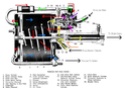
There are a ton of different models and sizes of Hydrovacs so they are not all the same.
Open the image in a new tab and follow along:
As pressure is applied to the brakes, fluid is passed into the Hydro-Vac (yellow).
It by-passes the hydraulic brake piston (# 20, thanks to the check ball), and pressure goes through the lines to the wheel cylinders.
At the same time it also passes through a pathway in the unit and applies pressure to (# 10) the control valve hydraulic piston.
As more pressure is applied to the brakes, the control valve piston pushes up on the metal rod on the rubber diaphragm (# 7).
The metal portion of the diaphragm has an air pathway through the center which allows air flow circulation throughout the unit
(through the tube (# 9) to the rear of the power cylinder piston). The atmospheric / vacuum valve (# 8 and # 13) is a two part valve
located above the diaphragm. It blocks air coming into the Hydrovac due to the spring (# 14) under the intake tube. Brake pressure
changes cause the vacuum valve to seat on the rubber diaphragm (shown in pink), sealing the air passage through it and effectively
blocking any air coming into the power cylinder (# 1) between the ports (# 6) located in the end plate of the unit and the connecting tube (# 9).
As pressure builds and the diaphragm is pushed even further forward, the atmospheric valve portion opens (shown in purple)
allowing air to enter the power cylinder (air path shown in green) and letting the vacuum from the engine pull the power cylinder piston (# 2)
forward which pushes the hydraulic brake piston (# 20) into the hydraulic cylinder (# 22).
The check ball has pressure from the brake lines pushing back against it now (orange) and seats inside the piston allowing no brake
fluid to pass by it back into the master cylinder. Therefore, the piston pushes more brake fluid forward in the lines and braking power increases.
The whole system uses brake pressure to overpower the springs and engage / disengage the control body valves.
The reason this system works the way it does is that the vacuum created by the engine is able to travel throughout the Hydrovac unit
(shown in red). Therefore with vacuum in front of and behind the power piston, there is equal pressure on both sides.
So until the valves close off that circulation and opens the air intake, the power cylinder piston won't move. Closing one valve stops that
circulation throughout the unit. Opening the intake allows the cylinder to pull air from behind so the vacuum can pull the power cylinder
piston forward.
Did you get all that? Its a little confusing.
(Above courtesy of J. Erickson)
Re-manufacturer links;
http://brakematerialsandparts.webs.com/http://www.karpspb.com/http://www.pwrbrake.com/http://priorautomotive.com.c1.previewmysite.com/http://www.dspartscompany.com/http://www.bepco.biz/index.htmhttp://precisionrebuilders.com/